How to fit secondary charge socket to Battery A
This to enable batteries to be charged away from the scooter, or to connect any 24 Volt lights, etc.
Ebay listings are always changing, but if you search for "3 XLR Charging Port Socket" you may find exactly what you need, with wires already attached.
If you cannot source a socket with rotating cover, go for a plain XLR female chassis socket and separate cover
(CPC Farnell parts CN00349 and AV18052)
or search Ebayfor XLR 3 pin female panel mount socket and XLR Socket cover cap
1. Unscrew outer cover to trip switch reset button and ensure reset is free to move out of casing - or else trip switch button can break off - Doh!
2. Turn Battery "A" upside down and Use 6 inch X head screwdriver (PZ2 or PZ3) to remove all visible screws (7 long + 2 short).
3. With point of sharp knife locate 2 hidden screw holes under velcro (one hole each side of casing),
cut slot in Velcro and undo last 2 screws (leave them under velcro).
4. Turn battery right side up and carefully remove cover, watching out for that trip switch (broken in photo).
Slide black insulating boot off negative battery post to expose nut and bolt.
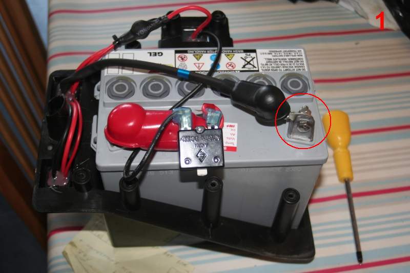
5. Get 12 inches of black insulated 10 amp wire & solder/crimp on a terminal with hole big enough to take bolt on neg. battery post.
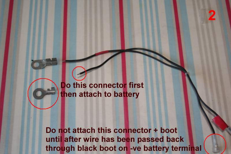
6. Attach this wire to neg. battery post and pass back through black insulating boot.
7. Optional female spade connector + cover can be attached to other end of wire (see photo 5 - else use choc block).
8. Cut open insulation sleeve (CAREFULLY so as to re-use it) that covers Y junction on red lead, to expose nut & bolt.
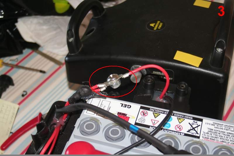
9. Undo nut & bolt, then solder lead from in-line fuse holder onto existing terminal that goes to Battery B.
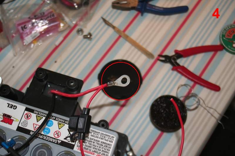
10. Reconnect terminal to nut & bolt Y junction and restore insulation (see photo 5).
11. Optional female spade connector + cover can be attached to lead from fuse holder, to match length of new black wire from step 5.
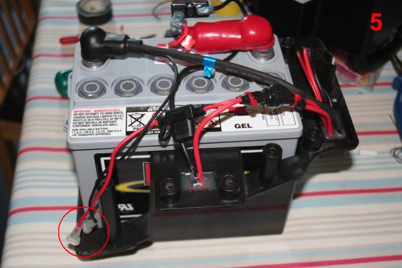
12. That completes mods to the wiring harness - now to fit the new charge socket to the upper casing
13. To prepare new socket, remove 3 way header shell, cut off centre green lead (unused), and cut off crimp connectors.
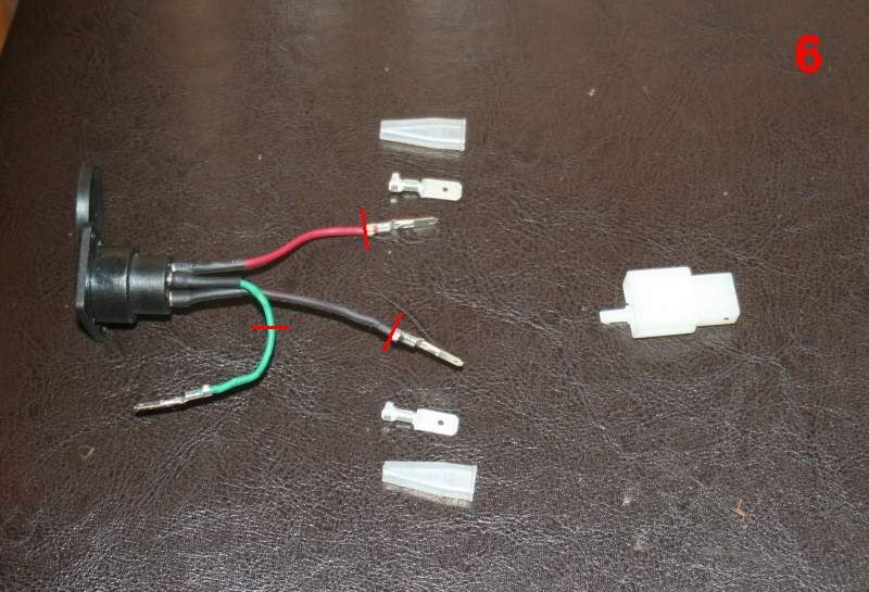
14. Solder or crimp on male spade connectors to black and red leads, with covers that mate to those you fitted earlier.
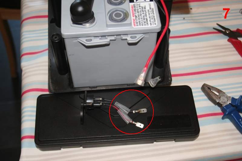
15. Time to drill the cover SLOWLY with 21mm hole saw & enlarge to fit socket (22mm) also a 6.5mm hole for spring-loaded
pivot for waterproof cover - then 2mm holes for 2 tiny countersunk self-tappers to secure socket onto battery casing.
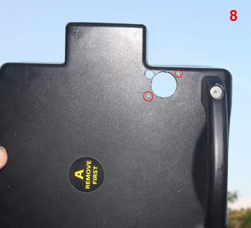
16. A little silicon sealant around lip of socket, and screw the socket into position.
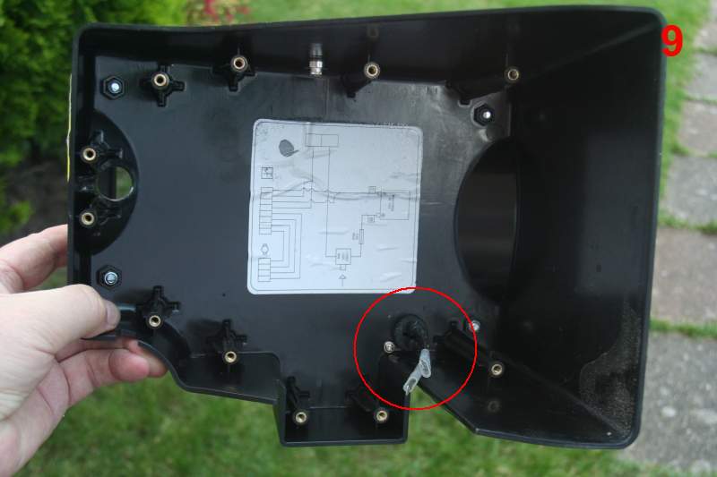
17. Time to connect your new charge socket...
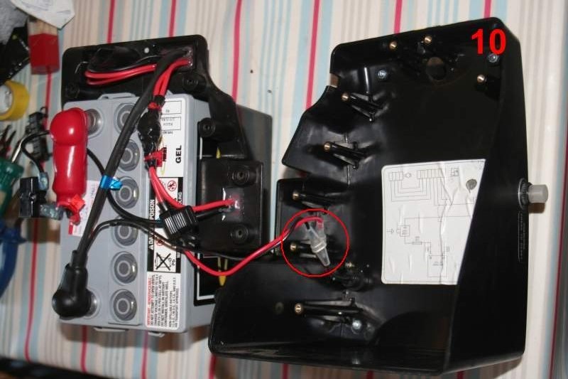
18. Reassemble (remembering that tricky overload trip and cover), replace all 11 screws, plug batteries A and B together, connect charger and test!
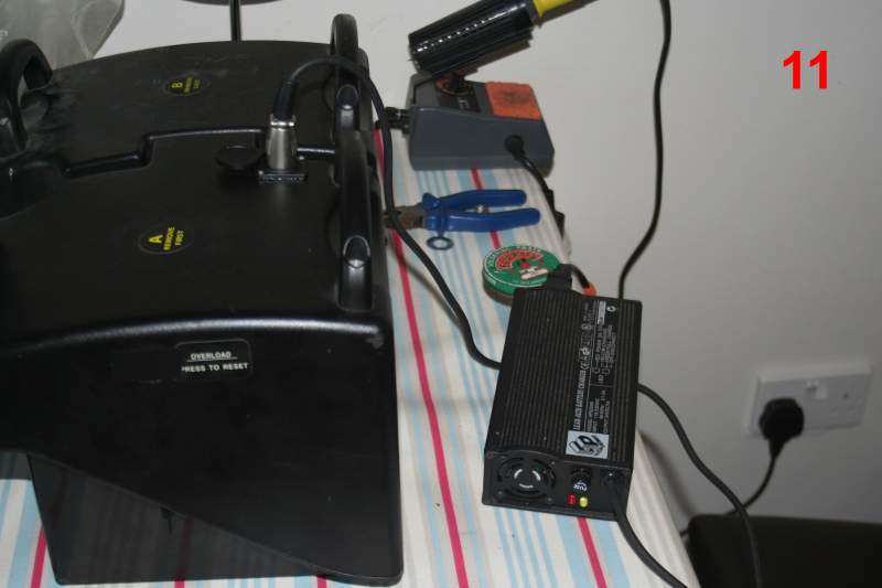
19. TADAA! Time for a beer!


